
Blinking a Blue Pill LED with Rust, from scratch
I wanted to figure out how microcontrollers work, so I wrote a small LED-blinking program in Rust, available on GitHub.
Most well-documented ways to program a microcontroller use libraries and generated code to make the job easier. If you’re trying to understand the hardware, you end up working backwards through those layers. Beginner-friendly material that starts from scratch is harder to find.
I know how compilers work well enough that using Rust wouldn’t get in the way. It also gives me a chance to learn more about Rust: raw pointers, volatile access, and what it takes to run without the usual startup code.
Leaving out the helper libraries is a good way to test vague knowledge. “The CPU starts executing after reset” sounds simple until you have to put its starting address in the right place.
The project has no external Rust dependencies. We’ll write to registers directly and look at the startup code and linker script. I’ll assume you already have a Blue Pill and know how to program. First we’ll get code onto the board, then follow it from reset to the LED.
The CPU, the microcontroller, and the board
The CPU in an STM32F103 is an Arm Cortex-M3. It executes instructions, uses a stack, and handles exceptions. ST combines that core with flash, RAM, timers, GPIO, and communication peripherals such as UART, SPI, I²C, and USB. That whole chip is the microcontroller.
Two chips can use the same CPU and have completely different peripherals. For example, QEMU’s Stellaris LM3S6965 board also has a Cortex-M3. It can execute the same relevant instructions, but its GPIO registers aren’t the STM32’s GPIO registers. Selecting a Cortex-M3 in an emulator doesn’t make it a Blue Pill.
The Blue Pill is the circuit board around the chip. It adds the regulator, crystals, USB connector, reset button, boot jumpers, LEDs, and accessible pins. This project targets an STM32F103C8T6 board with its user LED on PC13. That chip has 64 KiB of flash and 20 KiB of RAM.
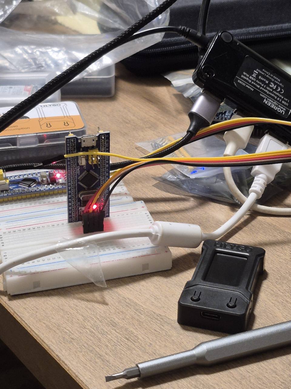
Check the marking on yours; Blue Pills don’t all come with the same chip.
The names we’ll use on the board are:
| Label or part | What it does here |
|---|---|
| PC13 | The GPIO pin connected to the built-in user LED and its resistor. |
| Power LED | Indicates board power. It is separate from the programmable LED. |
| SWDIO / DIO / PA13 | Debug data connection. |
| SWCLK / CLK / PA14 | Debug clock connection. |
| GND and 3.3 V | Ground and the board’s 3.3 V supply rail. |
| BOOT0 | Selects whether the chip starts from our flash program or another boot source. |
| NRST / RST | Reset signal; the reset button also restarts the chip. |
PC13 means pin 13 of GPIO port C, not pin 13 of the chip’s package. Similarly, PA13 and PA14 are the GPIO names of the pins used for debugging. Leave those two assigned to debugging for this example.
Where to find the information
You’ll want a few documents open. The board schematic, chip datasheet, and reference manual answer different questions. Searching for the right thing in the wrong PDF can waste a lot of time.
| Document | What to look up |
|---|---|
| Blue Pill board reference and schematic | Header pin labels, which pin the LED connects to, how the boot jumpers are wired, and where power comes from. |
| STM32F103x8/xB datasheet | The chip’s pinout, package, memory sizes, supply and I/O limits, and restrictions on particular pins. Check the PC13 through PC15 footnote. |
| STM32F1 reference manual, RM0008 | Memory map, boot modes, clocks, and peripheral registers. For this program, start with the memory map, Reset and clock control, and General-purpose and alternate-function I/Os. |
| Cortex-M3 Devices Generic User Guide, DUI0552 | The CPU’s reset sequence, stack, vector table, exceptions, core registers, and instructions. ST’s Cortex-M3 programming manual, PM0056 is another useful reference for this part. |
The Blue Pill reference is maintained by the STM32-base community. Use your seller’s schematic if it matches the board you bought; compare the components and pin labels before treating a generic drawing as an exact match.
The STM32 datasheet gives the details of a particular chip. RM0008 covers peripherals shared across a larger family, including parts with peripherals and pins your chip may not have. Keep both open. The datasheet tells you what you have; the reference manual tells you how to program it.
For the Cortex-M3, the programming guide is what we need here. The core’s reset and exception behavior comes from Arm. The electrical limits of the STM32 pins come from ST’s datasheet.
Finding a register without guessing
Suppose we want to enable GPIOC’s clock. In RM0008’s memory map, RCC starts
at 0x40021000. In the RCC chapter, the APB2 peripheral clock enable register,
RCC_APB2ENR, has offset 0x18. Its address is therefore:
0x40021000 + 0x18 = 0x40021018
The register’s bit diagram labels bit 4 IOPCEN, the I/O port C clock enable.
That’s where the address and 1 << 4 in our code come from. Check the access
type, reset value, and reserved-bit notes too. Don’t assume every register can
be read and written like RAM.
For the LED, start with the board schematic to find PC13 and see how it’s connected. Then check the datasheet for the pin’s restrictions, and RM0008 for the GPIO configuration and set/reset registers. You can jump straight to the relevant chapters; there’s no need to read the whole manual first.
Other docs
The chip’s product documentation page also lists its errata. Those describe known hardware bugs and workarounds. Match them to your part and silicon revision if a peripheral isn’t behaving as documented.
Use the documentation for your exact debug probe for connector pinouts and power wiring. Black Magic’s firmware variant matters too; we’ll get to that in the setup instructions.
For the Rust side, the Embedonomicon walks through building
an embedded program from scratch. The libopencm3 GPIO definitions
and cortex-m-rt source are also useful to read when you’re stuck.
You can study how a library does something without adding it as a dependency.
The Rust reference explains what #[used] retains, and the
standard-library docs explain what write_volatile guarantees.
For link.x, use the GNU ld linker-script manual to look up
MEMORY, SECTIONS, and KEEP. Rust’s bundled linker is LLD, which implements
this script syntax; its implementation notes describe differences
from GNU ld. You don’t need to install a second linker to read its manual.
Get the program onto the board
A debug probe connects the computer to the target microcontroller. The computer talks to the probe over USB. The probe talks to the target over SWD, Arm’s Serial Wire Debug interface. That lets a debugger halt execution, inspect memory, and arrange for a program to be written to flash.
We’ll use either an ST-Link or another Blue Pill running Black Magic firmware:
Computer → USB → ST-Link → SWD → target Blue Pill
                   ↑
           controlled by OpenOCD

Computer → USB → Black Magic probe → SWD → target Blue Pill
                         ↑
                GDB connects directly
OpenOCD is the host program that controls the ST-Link. Black Magic includes a GDB server in the probe’s firmware, so GDB connects to it directly.
I verified the Blue Pill running Black Magic route on my hardware: connecting to the target, flashing, and checking the written firmware. The ST-Link/OpenOCD instructions follow the tools’ documentation and should work, but I haven’t verified them on hardware. My Black Magic probe already had its firmware installed; preparing a blank probe is a separate prerequisite.
The target’s USB connector can supply power, but our firmware doesn’t implement USB. A stock STM32F103’s factory bootloader doesn’t provide USB flashing either. You can install an additional USB bootloader, but this guide uses SWD.
Build once, then choose your probe
The commands below assume Linux. The Rust project also builds on macOS and Windows; probe permissions and device paths differ.
Install rustup if necessary, then run:
git clone https://github.com/unmanbearpig/blinky-from-scratch.git
cd blinky-from-scratch
git checkout --detach d518188bb144e7dab077e27b4d3de7388461177a
rustup toolchain install 1.96.1 --profile minimal \
  --component rustfmt --component clippy --target thumbv7m-none-eabi
cargo build --release --locked
The checkout selects firmware revision d518188, used for the code,
disassembly, and sizes in this article.
rust-toolchain.toml pins that compiler version. The target
thumbv7m-none-eabi selects the Cortex-M3-compatible instruction set and
bare-metal environment. .cargo/config.toml selects that target and passes
link.x to Rust’s bundled linker. Building doesn’t require Arm GCC.
The output is:
target/thumbv7m-none-eabi/release/blinky-from-scratch
This is an ELF file, containing the program and information about where its parts belong in memory. Both flashing tools below understand ELF. They can use those addresses directly, so you don’t need a raw binary or a separate flash address.
Use the release build. The delay is a busy loop, and compiler optimization affects its timing. We’ll inspect that loop later.
Wire the target
Disconnect power while attaching wires. Set the target’s BOOT0 jumper to 0, so it boots our program from flash after reset. BOOT1 doesn’t affect this mode.
Both probes need these connections:
| Probe signal | Target Blue Pill |
|---|---|
| SWDIO | SWDIO / DIO / PA13 |
| SWCLK | SWCLK / CLK / PA14 |
| GND | GND |
| NRST, if available | NRST / RST, optional for normal programming |
Read the labels on your probe. Connector layouts vary, especially on ST-Link clones. Connecting NRST can help recover a target whose existing firmware interferes with normal debug access; my Black Magic setup worked without it.
Power wiring depends on the probe, so follow the relevant section below.
Option A: a Blue Pill running Black Magic
My probe runs Black Magic’s SWLINK firmware, v1.6.1-409-g7a595ea. On that
build, PA13 and PA14 are the probe’s connections to the target:
| Probe Blue Pill | Target Blue Pill |
|---|---|
| PA13 / SWDIO | PA13 / SWDIO |
| PA14 / SWCLK | PA14 / SWCLK |
| GND | GND |
| 3.3 V supply pin | 3.3 V supply pin |
The probe received USB power from the computer and supplied the target through that 3.3 V connection. The target had no separate USB supply. This describes my two-board setup; check the power-output capability before using another probe to supply a target.
The firmware variant matters. Other Black Magic builds for a Blue Pill can use different output pins. Check the supported hardware notes and the SWLINK notes for this revision.
If your second Blue Pill is blank, install Black Magic before using it as a probe. You’ll need another programming method, such as an existing ST-Link, or a suitable 3.3 V USB-to-UART adapter using the STM32’s factory serial bootloader. That bootloader requires a different boot-jumper setting from the target’s normal flash boot.
Follow the Black Magic build and installation documentation for the chosen hardware variant. Its pins, bootloader arrangement, and firmware addresses matter. I haven’t verified a fresh probe installation for this guide.
On the computer, install an Arm-capable GDB, commonly named arm-none-eabi-gdb
or gdb-multiarch. An ordinary host GDB may only support your computer’s CPU.
Check the one you plan to use:
arm-none-eabi-gdb -q -batch -ex 'set architecture arm'
If it rejects arm, use a debugger built with Arm support. The Rust toolchain
builds the firmware but doesn’t supply this debugger. Substitute your debugger’s
name in the commands if you’re using gdb-multiarch.
Black Magic exposes two USB serial interfaces on Linux. One speaks GDB’s remote protocol; the other is an optional UART bridge. Find the stable names:
ls -l /dev/serial/by-id/*Black_Magic*
The GDB interface ends in -if00. Use it rather than a remembered name such as
/dev/ttyACM0, since the tty numbering can change after reconnecting the probe.
Your user needs permission to open the serial device. If it belongs to the
dialout group, add yourself to that group using your system’s administrator
command, then log out and back in. For example:
sudo usermod -aG dialout "$USER"
Some distributions use another group or a udev rule. Check the device’s ownership. You shouldn’t need to run GDB as root.
With one Black Magic probe connected, find its GDB interface:
BMP_GDB_PORT=$(find /dev/serial/by-id -maxdepth 1 -type l \
  -name '*Black_Magic*if00' -print -quit)
printf '%s\n' "$BMP_GDB_PORT"
Check that this prints the expected path, then open the connection with the ELF loaded in GDB:
arm-none-eabi-gdb -q \
  -ex "target extended-remote $BMP_GDB_PORT" \
  target/thumbv7m-none-eabi/release/blinky-from-scratch
Scan for a target:
(gdb) monitor swdp_scan
My scan found target 1 as STM32F1 medium density M3/M4. Check that yours
finds the intended target before attaching:
(gdb) attach 1
If you want to preserve the existing firmware, save the project’s 64 KiB flash range before overwriting it:
(gdb) dump binary memory blue-pill-before-blinky.bin 0x08000000 0x08010000
This requires the target to permit flash reads. It saves that address range, not the option bytes or necessarily all the flash on an unknown chip.
Now flash the program, read it back for comparison, and reset the target:
(gdb) load
(gdb) compare-sections
(gdb) kill
(gdb) quit
load replaces firmware in the target’s flash. Inspect the compare-sections
output: a mismatch can produce a warning without giving a batch GDB command a
failing exit status. For the current build, my comparison reported:
Section .vector_table, range 0x8000000 -- 0x80000ec: matched.
Section .text, range 0x80000ec -- 0x8000284: matched.
On Black Magic, kill detaches and resets the target to start the program.
The probe’s GDB documentation describes this behavior.
Option B: ST-Link and OpenOCD
You can power the target from its USB connector and connect the ST-Link separately to the computer. Wire SWDIO, SWCLK, and GND as shown above.
If the probe has a target voltage reference input, often labelled VTref or VAPP, connect it to the target’s 3.3 V rail. It tells the probe what voltage the target uses; it does not supply power.
Some probes instead provide a 3.3 V power output. A documented, suitable output can power the target’s 3.3 V pin, in which case leave the target’s USB power disconnected. Check your specific probe. Use one target power source, and don’t connect 5 V to the target’s 3.3 V rail or debug signals.
Install OpenOCD and its supplied Linux udev rules using your distribution’s instructions. The rules let your user access the probe. Reload them and reconnect the probe as directed by the package.
From the project directory, run:
openocd \
  -f interface/stlink.cfg \
  -f target/stm32f1x.cfg \
  -c 'program target/thumbv7m-none-eabi/release/blinky-from-scratch verify reset exit'
The first configuration describes the probe; the second describes the target
family. program writes the ELF, verify checks it, reset restarts the chip,
and exit closes OpenOCD. This replaces the firmware currently in flash.
The command follows OpenOCD’s documentation. Let the supplied configuration choose its transport, since OpenOCD versions differ in which ST-Link driver they use. This is the route I haven’t tested on hardware.
Check the result
The current program should repeat one flash, a gap, two flashes, a gap, three flashes, and a longer pause. Watch the PC13 user LED, not the steady power LED. On my board, the LED blinked as expected.
If the computer can’t open the probe, check host access first: USB permissions for ST-Link, or the serial interface and permissions for Black Magic. If the probe opens but can’t find the target, check target power, shared ground, SWDIO, SWCLK, and the pin assignment of your particular probe firmware.
If programming and verification succeed but the LED doesn’t blink, check BOOT0, reset the board, and confirm its user LED is connected to PC13. A flash comparison establishes that the bytes arrived, not that the LED wiring matches.
Who calls main?
On a desktop, the loader and runtime set things up before main starts.
Here we’re running without an OS, so we have to do the setup ourselves.
These attributes turn off Rust’s usual standard library and entry setup:
#![no_std]
#![no_main]
no_std keeps Rust’s core library but leaves out the usual standard library.
no_main opts out of the normal entry machinery. We can still call a function
main; we just have to arrange for execution to reach it.
A reset handler that just calls main looks plausible:
pub unsafe extern "C" fn Reset() -> ! {
    main()
}
But the CPU still needs a way to find Reset, and main may expect its
global variables to have been initialized. Let’s set those up.
Give the CPU a starting point
When the STM32 boots from flash, it maps the start of flash into the boot address space. The Cortex-M3 reads two 32-bit words from there. The first is the initial stack pointer. The second gives the reset-handler address.
That means the image can’t just begin with arbitrary machine instructions. Its first words must have the structure the CPU expects. They begin the vector table, whose later entries give handler addresses for exceptions and interrupts.
Our linker script, link.x, describes where the memory is:
MEMORY
{
  FLASH (rx)  : ORIGIN = 0x08000000, LENGTH = 64K
  RAM   (rwx) : ORIGIN = 0x20000000, LENGTH = 20K
}

__stack_top = ORIGIN(RAM) + LENGTH(RAM);
The initial stack pointer is 0x20005000, the address just above RAM. The
stack grows downward into it. Inside the script’s SECTIONS block, we put
the vector table at the start of flash:
.vector_table ORIGIN(FLASH) :
{
  __vector_table = .;
  LONG(__stack_top);
  KEEP(*(.vector_table.reset_vector));
  KEEP(*(.vector_table.exceptions));
  KEEP(*(.vector_table.interrupts));
} > FLASH
The dot is the linker’s current address. LONG emits the initial stack pointer
as a 32-bit value. The next entry comes from this Rust static:
#[used]
#[unsafe(no_mangle)]
#[unsafe(link_section = ".vector_table.reset_vector")]
static RESET_VECTOR: unsafe extern "C" fn() -> ! = Reset;
It holds the reset function’s address. link_section puts it in the named
section; the linker script places that section after the stack pointer.
no_mangle preserves the symbol name, extern "C" specifies the calling
convention, and ! means the handler never returns. The toolchain encodes the
handler address for Arm’s Thumb instruction state.
Rust’s #[used] keeps the static in its object file, but the
linker can still discard it. KEEP prevents that second step. No Rust code
has to call through RESET_VECTOR; the CPU reads it on reset. The toolchain
needs to keep it even though ordinary code doesn’t refer to it.
The script also contains ENTRY(Reset), which records the entry point in the
ELF. The chip doesn’t read an ELF header after reset. It reads the table we
placed in flash.
Give global variables their initial values
Imagine adding a writable global whose initial value is 123. Its working
storage must be in RAM so the program can change it. But RAM doesn’t remember
123 across power cycles. A copy of that initial value must live in flash,
and startup must copy it into RAM on each reset.
A zero-initialized global has the same requirement to start with the right value. We can save flash space by recording the RAM range and clearing it, instead of storing a copy of all those zeroes.
These jobs correspond to the usual sections:
| Section | Contents | Startup’s job |
|---|---|---|
.text |
Executable code in flash | Execute it in place. |
.rodata |
Read-only constants in flash | Leave them in flash. |
.data |
Variables in RAM with initial values stored in flash | Copy the initial bytes into RAM. |
.bss |
Variables in RAM that must start at zero | Clear the range. |
That one-line Reset handler skips all of this. A blink can still work if
there’s no global storage to initialize. Constants can become immediate values
in instructions, and local values can live in CPU registers or on the stack.
Add a global that really occupies RAM, and you need more startup code even if the LED loop stays exactly the same. The blink didn’t test that part.
Our handler copies .data and clears .bss before calling main.
The linker provides the range boundaries and the source address of the initial
data through symbols such as __sdata, __edata, and __sidata. The handler
also sets the vector-table address register so later exceptions use our table
directly in flash.
One part still needs care before extending this example: the memory-init
loops are written in Rust. The Embedonomicon recommends assembly for this
stage because of Rust’s memory-model assumptions before
global memory is initialized. This blink has empty .data and .bss, so it
doesn’t test those loops with actual variables. Review that code before adding
globals, or use a maintained startup implementation such as
cortex-m-rt.
Leave somewhere to go when things break
An interrupt lets a peripheral request CPU attention. Exceptions also include faults detected by the processor. When one occurs, the CPU looks up the appropriate handler in the vector table.
You could supply just the stack pointer and reset-handler address and get a program started. But if a fault occurs, the CPU will still look for its handler at the defined offset in the table. It doesn’t know you stopped writing the table after two entries.
Our table includes the core exception entries and 43 peripheral interrupt entries for this STM32F103 target. The default handler loops forever, giving you a known place to inspect with GDB. We don’t enable peripheral interrupts for the blink.
Rust panics have a separate handler that also loops forever. There’s no terminal to print to or OS to return an exit status to.
When a pointer refers to hardware
Once execution reaches main, it has to configure GPIOC and change PC13.
These operations use memory-mapped registers: addresses where loads and stores
interact with peripheral hardware.
The STM32F1 reference manual gives us these addresses and bit meanings:
| Register | Address | What it controls |
|---|---|---|
RCC_APB2ENR |
0x40021018 |
Peripheral clocks, including the GPIOC clock. |
GPIOC_CRH |
0x40011004 |
Configuration of GPIOC pins 8 through 15. |
GPIOC_BSRR |
0x40011010 |
Commands to set or reset GPIOC output bits. |
In Rust, we describe an address as a raw pointer:
const GPIOC_BASE: usize = 0x4001_1000;
pub const GPIOC_BSRR: *mut u32 = (GPIOC_BASE + 0x10) as *mut u32;
This doesn’t allocate anything. It points at an address the hardware has
already assigned. The u32 selects a 32-bit access. usize would happen to
have the same width on this target, but the register’s width comes from the
chip specification. Use the type that matches it.
Unsafe doesn’t mean volatile
You might try enabling GPIOC with an ordinary pointer operation:
*RCC_APB2ENR |= RCC_APB2ENR_IOPCEN;
An unsafe block permits that raw-pointer access. It doesn’t tell the compiler
that the address is a peripheral or that the access must reach it.
Consider two assignments through an ordinary &mut u32:
*cell = 1;
*cell = 2;
If nothing can observe the first value, the compiler can remove the first
assignment. The final value is still 2, and the ordinary program’s observable
behavior is unchanged.
A peripheral can observe something different. Each write might start a timer, acknowledge an interrupt, or change an output. Switching an LED on and then off is different from only switching it off, even if the program never reads anything back. A write whose value looks redundant can still be an action we need the hardware to perform.
Rust’s read_volatile and write_volatile express that the
accesses themselves are observable. For the small example, the volatile
version is:
unsafe {
    core::ptr::write_volatile(cell, 1);
    core::ptr::write_volatile(cell, 2);
}
Compiling these small examples with the project’s compiler and Arm target at optimization level 3 produced one store for the ordinary version and two for the volatile version.
We use volatile accesses for the hardware registers. These still
require unsafe: the address, access width, alignment, and hardware setup
must be correct. Volatile access supplies an observable operation, not a check
that we chose the right peripheral.
It also doesn’t make a sequence of accesses atomic. Preserving a read and a write is separate from preventing an interrupt from doing something between them. We’ll run into that when changing an output.
Powering a chip doesn’t enable every peripheral
Peripherals have separate clock gates. The CPU can be running while GPIOC’s
clock is disabled, so first we set its enable bit in RCC_APB2ENR:
RCC_APB2ENR.write_volatile(RCC_APB2ENR.read_volatile() | RCC_APB2ENR_IOPCEN);
let _ = RCC_APB2ENR.read_volatile();
These accesses run inside main’s unsafe block. RCC_APB2ENR_IOPCEN is
1 << 4. The read-modify-write preserves other enable bits. The following
read provides a delay for the enable write to reach the peripheral before
we access GPIOC.
We leave the CPU clock at its reset configuration, using the internal 8 MHz oscillator. The STM32F103’s advertised maximum speed requires configuring the clock tree. Its external crystal isn’t needed for this program.
Configuring one pin can change other pins
GPIO pins can be inputs, outputs, or connections to other peripherals. We want PC13 to be a general-purpose push-pull output, so the program can drive it high or low.
The configuration lives in GPIOC_CRH. This is one 32-bit register containing
eight four-bit fields, for pins 8 through 15:
pin:      PC15  PC14  PC13  PC12  PC11  PC10  PC9   PC8
bits:     31:28 27:24 23:20 19:16 15:12 11:8  7:4   3:0
Within each field, the two low bits select the mode and the two high bits
select the configuration. For our output, MODE = 10 and CNF = 00, giving
0b0010. That selects a general-purpose push-pull output in the 2 MHz mode.
The 2 MHz value describes the output-driver mode. It doesn’t set the CPU clock or make the LED blink two million times per second. PC13 has stricter drive limits than most pins on this chip, and the slow output mode is appropriate for the onboard LED.
So we could write this value to the register:
0b0010 << 20
PC13’s field starts at bit 20, so that sets it correctly. It also writes zeroes into every other field. Those zeroes select analog-input mode. They don’t mean “leave this field alone” or “drive this pin low”.
You might not notice while the LED is the only thing you’re using. Add something else to the port, and configuring the LED could change its settings.
We can preserve the other fields by reading the register, clearing only PC13’s four bits, and inserting our setting:
let shift = (LED_PIN - 8) * 4;
let config = GPIOC_CRH.read_volatile();
GPIOC_CRH.write_volatile(
    (config & !(0b1111 << shift)) | (GPIO_OUTPUT_PUSHPULL_2_MHZ << shift),
);
Here LED_PIN is 13 and GPIO_OUTPUT_PUSHPULL_2_MHZ is 0b0010. The formula
for shift accounts for this register beginning at pin 8 and allocating four
bits per pin.
Check the meaning of the zeroes you write, too.
Some registers hold state; others accept commands
Once a pin is an output, its output latch selects high or low. GPIO’s ODR,
the output data register, holds those latch states as bits. A natural approach
would be to read ODR, change the desired bit, and write the result back.
That approach has a catch when another part of the program can update an output between your read and write. Imagine this sequence:
- The main code reads the output register.
- An interrupt handler changes another output bit.
- The main code changes its bit in the old value and writes that value back.
The last write can undo the interrupt handler’s change. Volatile reads and writes would preserve all those operations, including the one that overwrites the newer state.
The GPIO hardware offers a different operation through BSRR, the bit
set/reset register. Its writes tell the peripheral which bits to change:
| Bits written in BSRR | Command |
|---|---|
| A one in bits 0 through 15 | Set the corresponding output high. |
| A one in bits 16 through 31 | Reset the corresponding output low. |
| Zeroes in both command bits for a pin | Leave that output unchanged. |
Changing one output takes a single write, and the other outputs keep their states. Our blink doesn’t enable interrupts, but this is why the hardware offers the operation.
There’s also BRR, a bit reset register. We don’t need it here because the
upper half of BSRR already lets us reset a pin. BSRR handles both directions.
Low turns this LED on
The board connects the LED and its resistor between the 3.3 V supply and PC13. Driving PC13 low lets current flow through the LED. Driving it high turns the LED off. This is what “active low” means here.
Our two commands are therefore:
// Reset PC13 low: LED on.
GPIOC_BSRR.write_volatile(1 << (LED_PIN + 16));

// Set PC13 high: LED off.
GPIOC_BSRR.write_volatile(1 << LED_PIN);
The first writes bit 29, which resets output 13. The second writes bit 13, which sets output 13. The register accepts those commands; it isn’t a variable whose final stored value we care about.
The program also sets the output latch high before switching PC13 from input to output mode. That way, it begins driving the pin in the LED-off state.
A loop iteration isn’t a CPU cycle
Switching the output immediately back and forth would be too fast to see. The delay in this project is a small loop around a no-operation instruction:
fn wait(iterations: u32) {
    for _ in 0..iterations {
        asm::nop();
    }
}
Each iteration also has to count and decide whether to repeat. In the release build, one delay loop looks like this, with a label substituted for its address:
delay:
    subs r1, #1
    nop
    bne delay
subs decrements the counter and updates the condition flags. bne repeats
while the result is nonzero. The counter selects how many iterations run,
not how many CPU cycles pass. Even counting instructions wouldn’t completely
settle the timing, because instructions and branches need not all take one
cycle.
The firmware uses 200_000 iterations as one timing unit. It turns the LED
on for one unit and off for one unit, grouping flashes into counts of one,
two, and three. The gaps between groups total three units, and the gap before
repeating totals seven. The code accounts for the off-time already spent
after the last flash when adding those longer gaps.
Those units aren’t microseconds. A hardware timer would be the next step for stable timing, or for letting the CPU do other work while waiting.
Check what the compiler actually produced
Using Rust still leaves the generated instructions available to inspect.
With LLVM’s llvm-objdump installed, run:
llvm-objdump --disassemble target/thumbv7m-none-eabi/release/blinky-from-scratch
You can find the delay loop and the stores that change the output. You can
also compare a source expression with its implementation. In this build, the
GPIO configuration mask became a bfi instruction, which inserts a bit field,
once the operands were in registers. Several operations in Rust source don’t
necessarily become several separate operations on the CPU.
The ELF also separates the program’s loaded sections from debug information. This build loads 236 bytes of vector table and 408 bytes of code, 644 bytes in total. The ELF file itself is larger because it includes debug symbols and other metadata. Keeping those symbols for GDB doesn’t put them all in microcontroller flash.
Try changing it
Change GROUP_FLASH_COUNTS in src/main.rs to [3, 2, 1], rebuild, and flash
again. The groups should now count down. Change UNIT to adjust their timing,
then compare the source with the generated instructions.
For a bigger change, replace the busy loop with a timer. RM0008’s clock tree and general-purpose timer chapters are the places to start. You’ll need to work out which clock feeds the timer and how its prescaler and counter turn that into the interval you want.